
You’ll master adjustable bracelet design by implementing parametric modeling for variable dimensions, utilizing precision measurement tools like digital calipers for accurate wrist sizing, and employing finite element analysis to test material stress points. Apply 3D assembly constraints for moving components, use NURBS surface modeling for smooth mechanisms, and leverage pattern functions for repetitive elements. Incorporate tolerance analysis with ±0.1mm precision, Boolean operations for interlocking parts, and photorealistic rendering for validation. These techniques will reveal professional-level results that transform your creative concepts into manufacturable jewelry pieces.
Parametric Modeling for Variable Bracelet Dimensions

When designing adjustable bracelets, parametric modeling transforms your workflow by letting you define dimensions through variables rather than fixed measurements.
You’ll set parameters for length, width, and thickness that automatically adapt to different wrist sizes. By establishing constraints between bracelet components, you guarantee that modifying one dimension triggers corresponding adjustments throughout your design.
Setting parametric dimensions for length, width, and thickness ensures your bracelet design automatically scales to any wrist size through intelligent constraints.
You can incorporate formulas to create complex features like adjustable clasps and intricate patterns without manual recalibration.
CAD software provides sliders and input boxes that let you modify parameters in real-time, giving you instant visual feedback as you make adjustments.
Make certain you export your parametric models properly to 3D printing software, preserving the precise dimensions and adjustability you’ve built into your design for flawless manufacturing results.
Material Stress Analysis and Testing Simulations
Building on your parametric foundation, material stress analysis becomes your next critical step in creating robust adjustable bracelets.
You’ll use finite element analysis (FEA) software to simulate real-world forces and loads, visualizing exactly where stress concentrates across your design.
Your testing simulations should evaluate:
- Material performance – Compare metals, polymers, and composites to find the ideal balance of durability and comfort
- Environmental factors – Assess how temperature changes and daily wear affect long-term performance
- Load distribution – Identify weak points in adjustment mechanisms and connection areas
Precision Measurement Tools for Wrist Sizing

You’ll need accurate wrist measurements to design adjustable bracelets that fit perfectly and look professional.
Digital calipers provide precise measurements at multiple wrist points, while flexible measuring tapes give you the circumference data essential for determining cord length.
Wrist sizing guides help you standardize measurements and account for comfort allowances that prevent circulation issues.
Digital Caliper Measurements
Digital calipers serve as the gold standard for achieving precise wrist measurements when designing adjustable bracelets in CAD software.
You’ll achieve accuracy within 0.01 millimeters, ensuring your digital designs translate to perfectly fitting physical pieces.
When measuring, position the caliper’s jaws gently against the wrist without compressing the skin. This technique provides accurate circumference readings that you can directly input into your CAD program. The LCD display makes recording multiple measurements effortless.
Consider these essential practices:
- Add 1-2 centimeters to measured wrist size for comfort and adjustability
- Calibrate your calipers regularly to maintain precision
- Record measurements immediately to avoid errors
Your CAD software will use these precise measurements to generate parametric models, allowing you to create adjustable mechanisms that accommodate the exact size variations you’ve measured.
Flexible Measuring Tape
Although digital calipers excel in precision, flexible measuring tape offers unmatched versatility when capturing wrist circumference for CAD bracelet design.
You’ll need this essential tool to achieve accurate measurements that accommodate various bracelet styles and designs effectively.
When measuring, position the tape snugly against your client’s wrist without overtightening, guaranteeing the best fit for adjustable bracelets. Measure at the widest point, typically just above the wrist bone, and record measurements in inches or centimeters for CAD input.
Take multiple measurements and calculate their average to eliminate discrepancies and variations.
Flexible measuring tapes, crafted from soft materials, conform naturally to the wrist’s contours, delivering superior accuracy compared to rigid tools. This conformity guarantees comfortable bracelet fit while providing precise dimensional data for your CAD modeling process.
Wrist Sizing Guides
How can you guarantee consistent bracelet sizing across multiple clients while maintaining design precision? You’ll need thorough wrist sizing guides that standardize your measurement process.
Document measurements using established size categories rather than relying solely on individual circumferences.
For accurate data collection, you should:
- Measure both wrists since they often differ in size, then use the larger measurement
- Add 1-2 inches to the base measurement for comfort and proper adjustability
- Use digital calipers for custom designs requiring exact specifications
Create reference charts that convert raw measurements into standardized small, medium, and large categories.
This approach streamlines your CAD workflow and guarantees consistent production outcomes.
Always measure at the wrist’s widest point, typically just above the wrist bone, using flexible measuring tape for reliable results.
3D Assembly Constraints for Moving Components
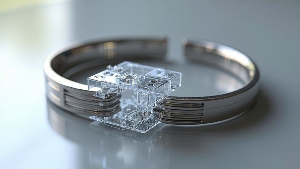
When designing adjustable bracelets with moving components, you’ll need to establish precise assembly constraints that control how each part interacts with others throughout the adjustment range.
You’ll primarily use coincident constraints to align sliding elements with guide tracks, ensuring smooth movement without binding. Concentric constraints keep rotating components properly centered on their pivot points, while distance constraints define minimum and maximum adjustment limits.
Set collinear constraints for sliding mechanisms to maintain proper alignment during extension and retraction.
Your CAD software’s assembly environment lets you simulate the full range of motion, helping you identify potential collisions between links or clasps. These constraints prevent manufacturing issues by ensuring components move freely within their intended parameters while maintaining structural integrity throughout all size adjustments.
Surface Modeling Techniques for Smooth Adjustable Mechanisms
You’ll need to master curved surface generation to create the flowing contours that make adjustable mechanisms both functional and visually appealing.
Smooth shift modeling becomes critical when connecting different bracelet segments, ensuring there aren’t any sharp edges or abrupt changes that could catch on clothing or cause discomfort.
Your mechanism housing design must seamlessly integrate these surfaces while maintaining the structural integrity needed for reliable adjustment operations.
Curved Surface Generation
Three fundamental techniques form the backbone of curved surface generation in CAD for adjustable bracelets: lofting, sweeping, and surface blending. These methods create smooth shifts between different features, guaranteeing your bracelet’s adjustable mechanism operates seamlessly.
You’ll achieve peak results by leveraging NURBS surface modeling, which provides exceptional flexibility and precision for complex curved surfaces. The control points and weight adjustments in NURBS allow you to tailor curvature specifically for ergonomic comfort and smooth operation.
Key advantages of curved surface generation include:
- Parametric flexibility – Modify curvature and dimensions instantly for rapid prototyping
- Surface continuity analysis – Visualize smoothness before production
- Ergonomic optimization – Ascertain comfortable wrist fit through precise curvature control
These techniques enable you to create adjustable bracelets that combine aesthetic appeal with functional excellence.
Smooth Transition Modeling
Building upon foundational curved surface generation, smooth adjustment modeling requires specialized techniques that address the mechanical demands of moving components. You’ll need to master NURBS for precise curvature control and surface continuity throughout your bracelet’s adjustable mechanism.
| Technique | Application | Benefit |
|---|---|---|
| NURBS Modeling | Curvature control | Seamless changes |
| Lofting | Cross-section bridging | Enhanced aesthetics |
| Fillet/Chamfer | Joint optimization | Stress reduction |
Lofting techniques help you create smooth profiles between different bracelet cross-sections, improving both visual appeal and adjustability. You should implement fillet and chamfer features strategically to reduce stress concentrations at critical joints, ensuring your design’s durability. Advanced rendering tools let you simulate adjustable mechanisms in motion, allowing you to visualize and refine change smoothness before production begins.
Mechanism Housing Design
Since adjustable bracelet mechanisms require precise housing to function properly, surface modeling becomes critical for creating enclosures that protect moving parts while maintaining smooth operation.
You’ll need to master NURBS techniques to achieve the continuous curves essential for ergonomic housing design.
When developing your mechanism housing, focus on these key elements:
- Tolerance management – Maintain ±0.1 mm tolerances to prevent excessive friction between components
- Parametric modeling – Use 3D parametric tools to easily modify dimensions and optimize internal component fit
- Stress simulation – Apply FEA during design phases to predict housing behavior under operational stress
Tools like SolidWorks or Autodesk Fusion 360 help you achieve precise curvature and surface finishes.
This guarantees your mechanisms operate smoothly without pinching or jamming, while the housing provides adequate protection for all moving parts.
Boolean Operations for Creating Interlocking Elements
When you’re designing adjustable bracelets with interlocking elements, Boolean operations become your most powerful CAD tools for creating precise, functional connections. The three primary operations—Union, Subtraction, and Intersection—each serve distinct purposes in your design process.
Use Union operations to combine separate components, ensuring seamless fits without gaps between interlocking pieces. This operation’s particularly valuable when merging multiple design elements into cohesive assemblies.
Subtraction operations excel at creating slots, notches, and cutouts that enable proper interlocking functionality. You’ll remove material precisely where adjustment mechanisms need clearance or where components must slide together.
Intersection operations help you identify overlapping areas between designs, allowing you to refine connections and verify that interlocking elements maintain structural integrity while functioning smoothly throughout the bracelet’s adjustment range.
Pattern and Array Functions for Repetitive Design Elements
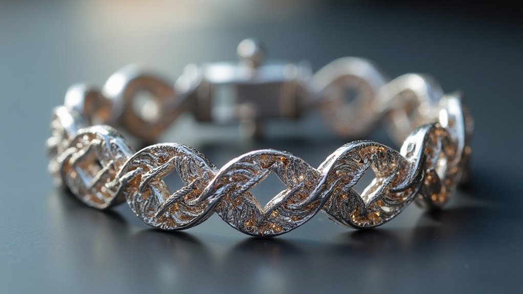
Pattern and array functions transform repetitive bracelet design work from tedious manual tasks into streamlined automated processes.
You’ll find these CAD tools especially valuable when creating adjustable bracelets with consistent spacing and geometric arrangements.
These functions offer significant advantages:
CAD pattern and array functions deliver unmatched parameter flexibility, dynamic updates, and time efficiency for modern bracelet designers.
- Parameter flexibility – You can easily adjust spacing, rotation, and scaling to achieve your desired aesthetic without recreating elements.
- Dynamic updates – Modifying one element automatically updates all instances, ensuring design consistency throughout your bracelet.
- Time efficiency – Quick iterations become possible as you experiment with different arrangements of beads, knots, or decorative elements.
When designing adjustable bracelets, you’ll use arrays to position identical features systematically.
This approach proves particularly effective for creating uniform bead patterns or evenly-spaced adjustment holes, allowing you to focus on perfecting individual components rather than repetitive placement tasks.
Tolerance Analysis for Optimal Fit and Movement
After establishing your repetitive design elements, you’ll need to assure these components work together smoothly through precise tolerance analysis.
Define acceptable dimensional limits to guarantee your bracelet components move freely without excessive friction or slippage. A typical tolerance range of ±0.5 mm provides the sweet spot between comfortable adjustability and structural integrity.
Use your CAD software’s simulation features to test assemblies with different tolerances. This’ll help you identify the ideal fit that balances ease of adjustment with durability.
Include rounded edges or chamfers in your designs—they’ll reduce stress concentrations at connection points and influence overall tolerance performance.
Analyze movement mechanics through CAD simulations to enhance cord length and flexibility, improving the user’s adjustment experience.
Rendering and Visualization for Design Validation
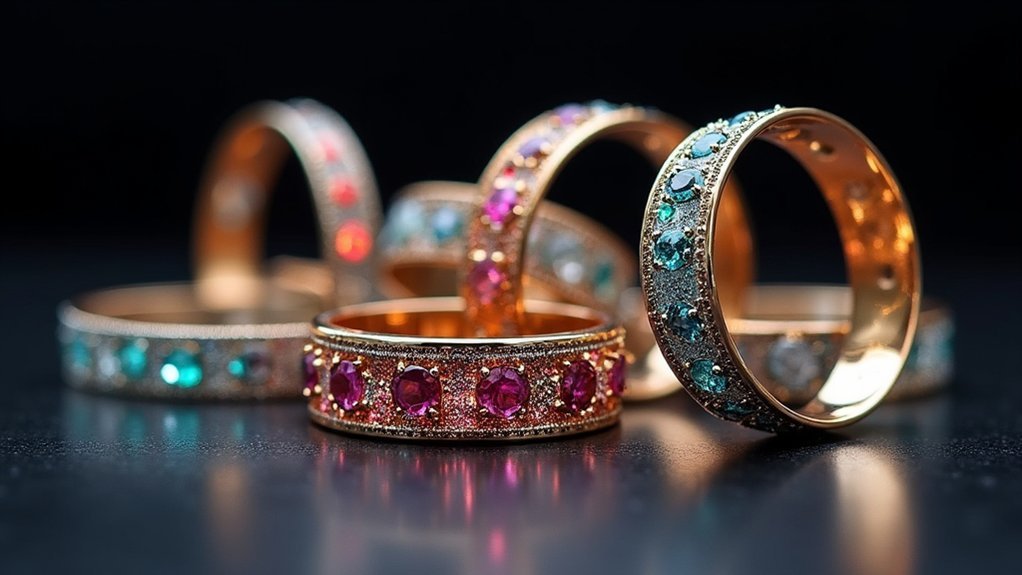
Once you’ve optimized your tolerance specifications, photorealistic rendering becomes your next critical validation step.
Photorealistic rendering serves as your crucial validation checkpoint after finalizing tolerance specifications for optimal design verification.
CAD visualization transforms your adjustable bracelet concepts into realistic representations, letting you evaluate materials, colors, and finishes before investing in physical prototypes.
Advanced rendering tools help you:
- Simulate light interaction with different materials to understand how your bracelet’s finish will appear under various lighting conditions
- Test adjustability mechanisms virtually, guaranteeing smooth functionality and aesthetic appeal
- Analyze structural integrity while maintaining visual design elements
Parametric modeling accelerates your design iterations, allowing quick dimensional adjustments while preserving your original intent.
You’ll catch potential issues early, from awkward proportions to mechanism conflicts.
This thorough visualization approach guarantees your adjustable bracelet performs flawlessly and looks stunning before production begins.
File Preparation for 3D Printing and Manufacturing
Several critical factors determine whether your adjustable bracelet design translates successfully from CAD model to physical product.
You’ll need to carefully scale your CAD file to match desired dimensions while incorporating tolerances for proper fitting and movement. Export your model using STL or OBJ formats, as they’re universally compatible with 3D printers and manufacturing software.
Before finalizing, inspect your model thoroughly for non-manifold edges or overlapping geometries that’ll cause printing complications.
Optimize material usage by considering print orientation and minimizing support structures for efficient manufacturing. Confirm snap-fit joints and adjustable clasps are properly dimensioned for functionality while maintaining aesthetic appeal.
These preparation steps guarantee your design won’t just look good on screen but’ll actually work as intended.
Frequently Asked Questions
How to Make an Adjustable Knot for a Bracelet?
Tie your strings together tightly at the top. Align two cord ends, tape them down, then use a separate string to create square knots around both cords for easy adjustment.
What Is the Best String for Sliding Knot Bracelets?
You’ll want smooth nylon or polyester cord between 1-2mm thick for sliding knot bracelets. These materials won’t fray and slide easily through knots. Avoid cotton since it absorbs moisture and weakens over time.
How to Tie the End of a Friendship Bracelet Adjustable?
Align both cord ends and tape them down. Use separate string to create tight square knots over the fixed cords. Cut excess string, leaving small tails, then seal knots with clear nail polish.
How to Make a Loop Knot for Bracelets?
Start by making an overhand knot with your string, leaving a long tail. Wrap the tail around the standing string, thread it through the created loop, then pull tight while adjusting the loop size.
In Summary
You’ve now mastered the essential CAD techniques that’ll transform your adjustable bracelet designs from basic concepts into precision-engineered accessories. By implementing parametric modeling, stress analysis, and tolerance calculations, you’ll create bracelets that fit perfectly and function flawlessly. Remember to validate your designs through rendering and prepare files properly for manufacturing. These ten techniques will consistently deliver professional-quality adjustable bracelets that meet both aesthetic and functional requirements.
Leave a Reply