
You’ll achieve perfect gemstone settings by mastering precise stone modeling with correct crown-to-pavilion ratios and maintaining proper clearances—0.2-0.3mm for diamonds, 0.3-0.5mm for colored stones. Apply the Rule of Thirds for systematic prong placement, position gallery wires at ideal depths, and use socket settings with Single Hole commands for efficient placement. Always overbuild by 2-3% to compensate for casting shrinkage, utilize pattern tools for multi-stone designs, and establish your stone positions before building the setting structure to guarantee flawless results that professional jewelers demand.
Understanding Stone Dimensions and Proportions in CAD Models

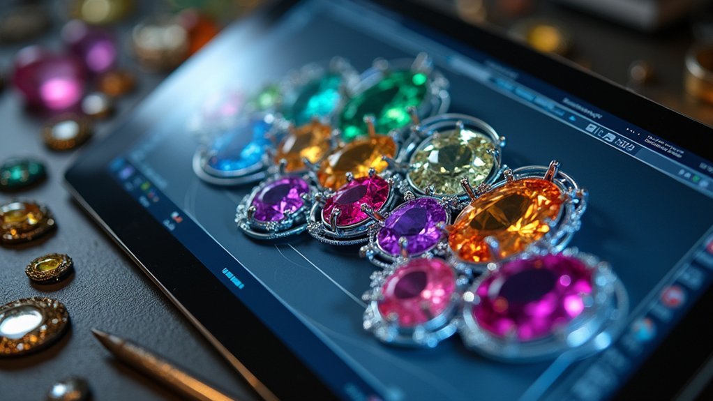
Precision becomes your foundation when modeling gemstones in CAD software. You’ll need to accurately replicate each stone’s dimensions, including crown height, pavilion depth, and girdle thickness to guarantee perfect setting compatibility.
Understanding gemstone proportions, particularly the crown-to-pavilion depth ratio, directly impacts your gallery wire placement decisions.
When positioning prong settings, you must account for specific spacing requirements. Diamonds need 0.2 to 0.3 mm clearance between the upper gallery wire and pavilion to prevent crowding during setting. Colored gemstones require greater spacing of 0.3 to 0.5 mm due to their natural irregularities.
Apply the Rule of Thirds to enhance aesthetic appeal by centering your gallery wire placement according to the stone’s proportions. This systematic approach guarantees both functional precision and visual harmony in your final design.
Applying the Rule of Thirds for Optimal Prong Placement
You’ll achieve professional-looking prong settings by applying the Rule of Thirds to divide the distance from your stone’s girdle to its culet into three equal sections.
Position your upper gallery wire at the center of the middle division while ensuring the wire thickness matches or exceeds that third measurement for proper structural support.
Create an elegant culet windowing effect by strategically spacing your upper and lower gallery wires to frame the stone’s bottom point without compromising the clean top-view appearance.
Girdle to Culet Division
When designing gemstone settings, applying the Rule of Thirds to the girdle-to-culet distance creates a systematic approach for ideal prong placement that guarantees both structural integrity and visual appeal.
You’ll divide the distance from your gemstone’s girdle to its culet into three equal sections. Center your upper gallery wire on the middle division to achieve balanced stone support.
The gallery wire thickness must match or exceed one-third of the girdle-to-culet measurement for adequate stability. Position the culet so it’s “windowed” between upper and lower gallery wires, enhancing both visibility and aesthetics.
From the top view, no gallery wires should be visible, maintaining your setting’s clean, elegant appearance in the final design.
Gallery Wire Positioning
Although gallery wire positioning might seem straightforward, mastering the Rule of Thirds transforms your prong placement from guesswork into precise engineering.
You’ll divide the distance from the stone’s girdle to its culet into three equal sections, positioning your upper gallery wire at the center of the middle division. This creates perfect alignment with your stone’s profile while maintaining structural integrity.
Your gallery wire thickness shouldn’t be less than one-third of this distance.
You’ll want to maintain 0.2-0.3mm spacing for diamonds and 0.3-0.5mm for colored stones to accommodate irregularities during setting.
The polishing process becomes more predictable when you guarantee gallery wires remain invisible from the top view, keeping focus on your gemstone rather than the mechanical elements.
Culet Windowing Technique
Three critical measurements determine your culet windowing success: girdle-to-culet distance, gallery wire thickness, and the precise positioning that creates an invisible support structure.
You’ll apply the Rule of Thirds by dividing this distance into equal sections, placing your upper gallery wire at the middle division’s center.
Your jewelry’s structural integrity depends on these four essential steps:
- Measure gallery wire thickness – it must equal or exceed one-third of the girdle-to-culet distance
- Create proper spacing – 0.2-0.3mm for diamonds, 0.3-0.5mm for colored stones
- Position the window strategically – culet must remain invisible from top view
- Test stone setting security – verify your main stone sits firmly without movement
This technique transforms ordinary prong settings into masterful displays of craftsmanship.
Creating Proper Gallery Wire Spacing for Different Gemstone Types
Since proper gallery wire spacing determines both the security and visual appeal of your gemstone setting, you’ll need to adjust your measurements based on the specific stone type you’re working with.
Proper gallery wire spacing is the foundation of secure, visually appealing gemstone settings that showcase your stones perfectly.
For diamonds, maintain 0.2 to 0.3 mm spacing between your upper gallery wire and the pavilion during your cut operation. Colored stones typically require more room—leave 0.3 to 0.5 mm to accommodate irregular cuts.
Apply the rule of thirds by dividing the distance from girdle to culet into three sections, then center your upper gallery wire on the middle division.
Your wire thickness should match or exceed this third measurement for structural integrity. Position the wire to window the culet between upper and lower gallery wires while keeping them invisible from the top view.
Building Custom Gallery Wire Profiles for Colored Gemstones
You’ll need to modify standard gallery wire profiles when working with colored gemstones to guarantee proper fit and visual appeal.
Start by adjusting the upper gallery wire to prevent excessive thinning while maintaining that essential round appearance your setting demands.
Focus on creating adequate space beneath the pavilion to prevent crowding, which can force higher settings and increase damage risk during the setting process.
Profile Modification Techniques
Crafting custom gallery wire profiles transforms the way your colored gemstones sit within their settings, guaranteeing each unique stone receives the precise support it deserves.
These profile modification techniques revolutionize your approach to making jewelry by addressing each gemstone’s individual characteristics.
When creating custom gallery wire, you’ll master these essential modifications:
- Shape matching – Design profiles that mirror your gemstone’s exact dimensions for flawless seating.
- Strategic thinning – Remove material carefully while preserving structural integrity and round appearance.
- Light enhancement – Evaluate gemstone profiles to maximize light reflection and brilliance.
- Irregularity accommodation – Customize profiles to handle unique stone variations without crowding.
These techniques guarantee your settings provide both security and visual appeal, preventing structural compromise while enhancing the stone’s natural beauty through proper support and ideal light performance.
Preventing Pavilion Crowding
Preventing pavilion crowding becomes your primary concern when building custom gallery wire profiles, as improper spacing can compromise both the stone’s security and visual performance.
You’ll need to maintain a 0.3 to 0.5 mm clearance between your upper gallery wire and the gemstone’s pavilion. This spacing accommodates shape irregularities while preventing unwanted contact that could damage the stone.
Focus on your wire thickness relative to the gemstone’s proportions. Your upper gallery wire should equal at least one-third of the distance from girdle to culet, ensuring adequate structural integrity without excessive bulk.
Proper spacing allows the culet to remain visible between upper and lower wires, creating an aesthetically pleasing appearance while maintaining the round wire profile that balances both functionality and visual appeal.
Maintaining Round Aesthetics
When modifying gallery wire profiles for colored gemstones, preserving the wire’s inherently round appearance becomes essential for maintaining the setting’s visual harmony. Custom modifications shouldn’t compromise the wire’s aesthetic integrity while accommodating unique gemstone shapes.
You’ll want to balance functionality with visual appeal through these key approaches:
- Maintain circular cross-sections – Keep the gallery wire’s round appearance intact even when creating custom profiles.
- Center upper gallery placement – Position it on the middle division of your stone’s height for perfect symmetry.
- Use adequate thickness – Follow rule-of-thirds dimensions to effectively window the culet while preserving roundness.
- Consider light reflection – Guarantee your modifications allow proper brilliance without distorting the wire’s natural form.
These techniques guarantee your colored gemstones sit securely while maintaining elegant, professional aesthetics.
Using Socket Settings and Hole Commands for Multiple Stones
Although traditional manual positioning methods can prove time-consuming and error-prone, socket settings combined with strategic hole commands offer jewelry designers a streamlined approach for placing multiple gemstones with precision. You’ll find the Single Hole command particularly effective when creating conical holes with zero depth—this technique matches your gemstone’s facets perfectly, ensuring secure fits during setting. The Multiple Holes command simplifies gemstone positioning while maintaining uniform sizing across all settings, dramatically enhancing your design efficiency.
For ideal results, implement the Combine|Cut operation by duplicating your gemstone model as a reference for accurate placement. The standard Hole command provides consistent positioning with easy adjustments and perpendicular alignment. Using patterns for multiple settings reduces complexity compared to manual methods, delivering superior precision.
Accounting for Casting Shrinkage in Setting Measurements
Since metal contracts during the cooling phase after casting, you’ll need to overbuild your gemstone settings by approximately 2-3% to account for this inevitable shrinkage.
Different metals require specific adjustments to your setting measurements. Platinum typically shrinks 1.5-2%, while gold alloys can shrink up to 2.5%.
Here’s how to master casting shrinkage compensation:
- Calculate exact shrinkage percentages for your chosen metal before finalizing dimensions
- Add dimples or locating features to guide precise gemstone placement after casting
- Adjust all critical dimensions based on your material’s specific shrinkage characteristics
- Perform test castings with similar materials to verify your gemstone settings fit perfectly
These proactive measures guarantee your stones sit securely without frustrating post-casting adjustments or costly remakes.
Positioning Stones First to Establish Design Foundation

Your CAD workflow becomes markedly more efficient when you start with stone placement rather than building the setting structure first. Positioning your main stone establishes the foundation that influences every subsequent design decision.
| Stone Type | Gallery Wire Space | Rule of Thirds Application |
|---|---|---|
| Diamond | 0.2-0.3mm clearance | Center on middle division |
| Sapphire | 0.3-0.5mm clearance | Balance visual weight |
| Emerald | 0.3-0.5mm clearance | Account for irregularities |
| Ruby | 0.3-0.5mm clearance | Custom profile seating |
| Accent stones | Variable spacing | Cohesive placement flow |
Begin with your focal stone’s exact position, then use precise measurements for gallery wire spacing. The Rule of Thirds guides upper gallery wire placement, ensuring balanced aesthetics. For colored gemstones, you’ll need custom gallery profiles to prevent excessive metal thinning while maintaining proper stone seating and visual appeal.
Creating Accurate Templates and Guides for Stone Placement
You’ll need reliable digital measurement methods to capture your gemstones’ exact dimensions before creating any CAD templates.
Your template design process should incorporate Matrix CAD’s precision tools, including dimples and markers that’ll guarantee consistent stone positioning across multiple settings.
Building effective placement reference systems means using the Single Hole command with zero depth to create conical holes that perfectly match each gemstone’s unique cut and profile.
Digital Stone Measurement Methods
Precision starts with accurate gemstone measurements, and digital tools like calipers and micrometers guarantee you’ll capture every critical dimension needed for flawless CAD templates.
These digital stone measurement methods transform jewelry making from guesswork into precision engineering.
Your measurement workflow should include:
- Girdle diameter mapping – Record the widest points where your setting will grip the stone
- Pavilion depth analysis – Measure how deep your mounting must accommodate the stone’s bottom
- Culet positioning data – Identify the exact center point for perfect alignment
- Facet angle documentation – Capture the precise angles that’ll interact with your prongs
Once you’ve gathered these measurements, input them directly into your CAD software.
This data becomes the foundation for socket settings with conical holes that match your gemstone’s cut perfectly, eliminating the trial-and-error approach that wastes time like an inefficient grinding wheel.
CAD Template Design Process
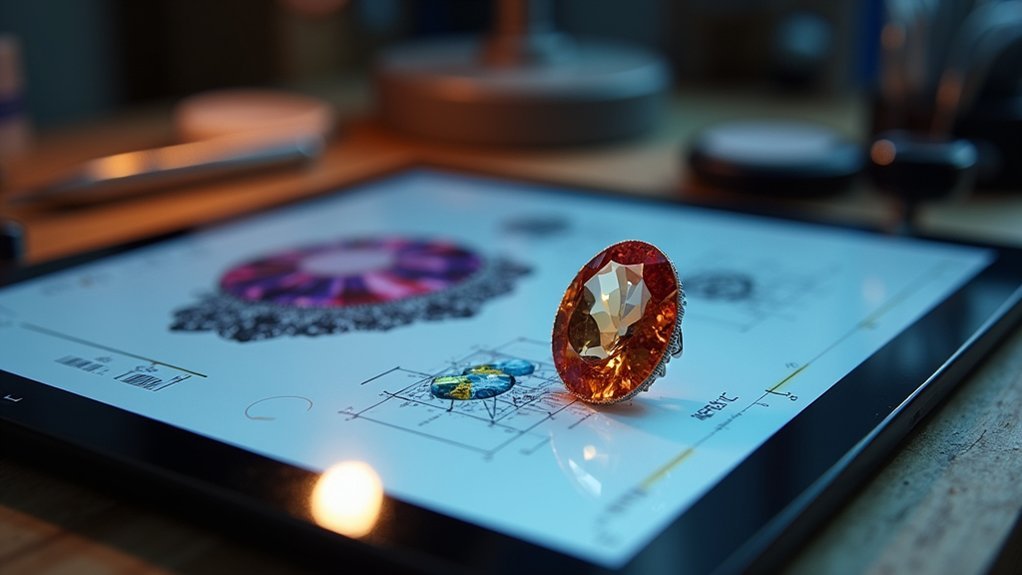
With your gemstone measurements in hand, the template creation phase transforms raw data into functional design elements that guide every aspect of your setting process.
Begin by precisely modeling the gemstone with accurate dimensions to guarantee ideal fit. Use the Combine|Cut feature to create socket holes that perfectly match the stone’s profile, keeping them perpendicular to the jewelry surface for consistent placement.
The Multiple Holes command streamlines your workflow when positioning multiple settings, maintaining uniform size and spacing throughout your design. Include dimples or markers in your templates to indicate exact gem placement locations.
Apply the Rule of Thirds when positioning gallery wire in your templates, guaranteeing the upper and lower wires effectively frame your gemstone while maintaining visual balance and design integrity.
Precision Placement Reference Systems
Once you’ve established your basic template dimensions, developing an extensive reference system becomes vital for achieving consistent gemstone placement across complex designs.
Your precision placement strategy relies on creating reliable reference points that guarantee every stone sits exactly where intended.
Build thorough reference systems using these proven methods:
- Create master gemstone models that establish perfect positioning standards across your entire project.
- Implement measuring divisions based on critical dimensions like girdle-to-culet distances for flawless uniformity.
- Deploy “Circular or Rectangular Pattern” tools to maintain consistent spacing that eliminates costly manual adjustments.
- Execute “Multiple Holes” commands with perpendicular alignment checks that ensure secure, professional-grade settings.
These gemstone settings reference systems transform complex multi-stone projects into manageable, repeatable processes that deliver exceptional results consistently.
Combining Pattern Tools for Efficient Multi-Stone Designs
Multi-stone jewelry designs require strategic use of pattern tools to achieve both efficiency and precision in your CAD workflow. You’ll find that Fusion 360’s Multiple Holes command creates uniform gemstone settings with consistent spacing across your design. When making complex arrangements, start by modeling your first setting hole with perfect perpendicular alignment to the jewelry surface.
| Tool | Function | Best Use Case |
|---|---|---|
| Circular Pattern | Radial duplication | Halo settings, circular bands |
| Rectangular Pattern | Linear/grid arrays | Tennis bracelets, geometric designs |
| Multiple Holes | Automated placement | Uniform pave settings |
Use Combine|Cut operations with duplicated gemstone models for precise socket creation. Developing macros for automated positioning reduces design time remarkably, especially beneficial when Platinum polishing requires exact tolerances during the polishing and making processes.
Optimizing Settings for Manufacturing and Hand-Finishing Processes
Efficient pattern tools become meaningless if your individual settings aren’t adjusted for the realities of manufacturing and hand-finishing work.
You’ll need precise measurements and thoughtful design choices to guarantee your CAD models translate seamlessly to finished pieces.
Consider these critical manufacturing guidelines:
- Maintain proper clearances – Leave 0.2-0.3mm space for diamonds and 0.3-0.5mm for colored stones between upper gallery wire and pavilion.
- Apply the Rule of Thirds for prong positioning, ensuring wire thickness matches calculated measurements for ideal visibility.
- Utilize custom gallery profiles to accommodate irregular colored gemstone shapes without excessive thinning.
- Implement socket settings using Single Hole commands for precise conical holes matching your cuts.
Your next step involves developing macros for gemstone duplication, streamlining both modeling and setting processes inside of the ring structure.
Frequently Asked Questions
What Is the Best Stone Setting?
You’ll find prong settings work best for diamonds with 0.2-0.3mm gaps, while colored gemstones need 0.3-0.5mm spacing. Apply the Rule of Thirds for ideal positioning and use custom gallery profiles for enhanced aesthetics.
What Is the Most Common Gem Setting?
You’ll find the prong setting is the most common gem setting. It uses four to six prongs to securely hold your gemstone while maximizing light exposure, making it perfect for engagement rings.
What Holds a Gem in Place?
You’ll find that metal prongs grip your gemstone at its girdle, securing it firmly in place. These prongs wrap around the stone’s widest part, holding it steady while allowing maximum light to enter and showcase brilliance.
In Summary
You’ve now got the essential CAD techniques to create flawless gemstone settings that’ll impress both clients and manufacturers. Remember to always start with accurate stone measurements and build your design from there. Don’t rush the process—proper planning and attention to detail in your CAD work will save you countless hours during production. Practice these techniques consistently, and you’ll develop the muscle memory needed for efficient, professional-quality jewelry design that stands out in today’s competitive market.


Leave a Reply